
Photonics & Optics
Optical mounts, kinematic stages, lens housings and detector brackets, machined to ±0.005 mm. An engineer reviews every order for surface finish, coating and tolerance stack-up before manufacture starts.
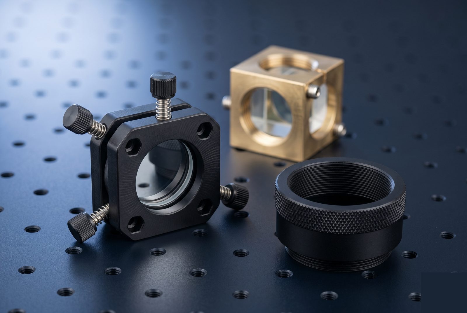
Photonics Components, Built to Spec
Each card gives the tolerance, material and finish these parts usually carry. Parts that are not listed are reviewed and quoted the same way.
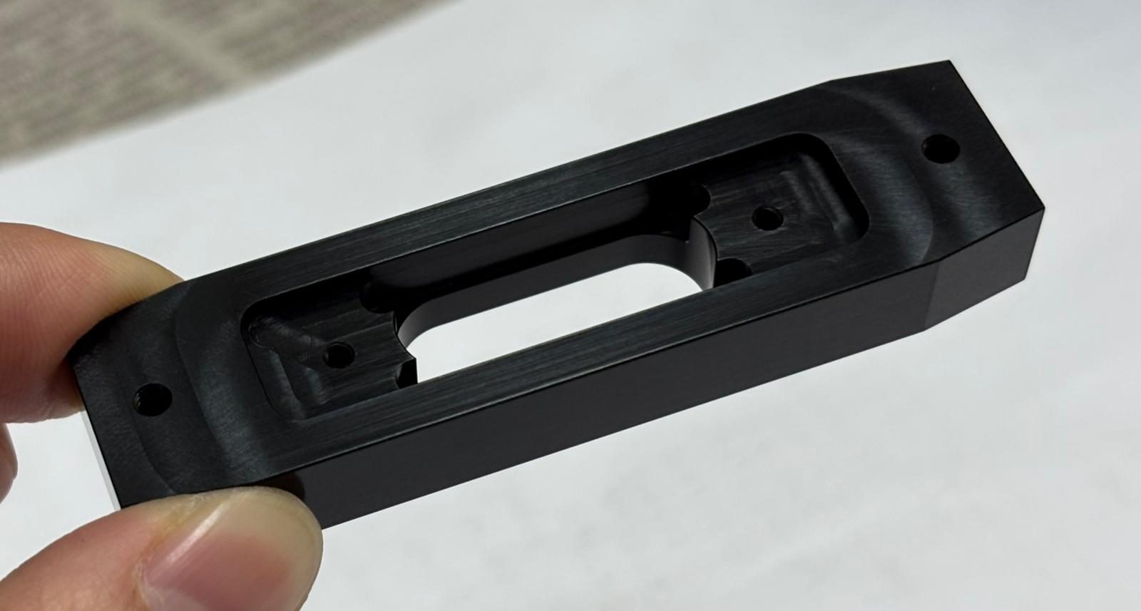
Lens Mounts and Tubes
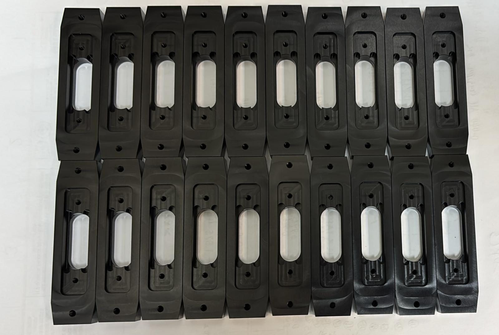
Kinematic Mounts
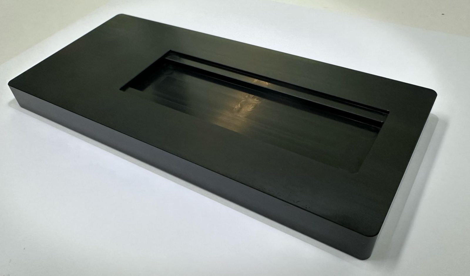
Filter and Beamsplitter Holders
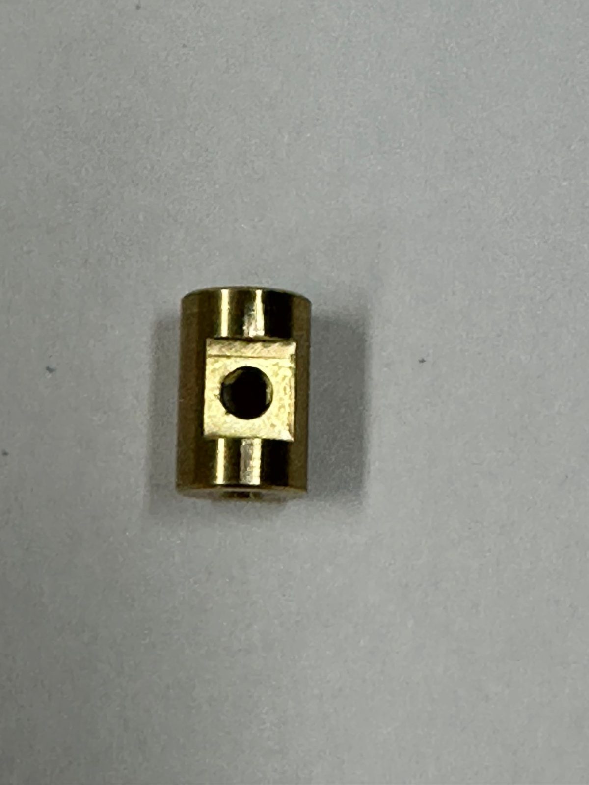
Detector and Sensor Housings
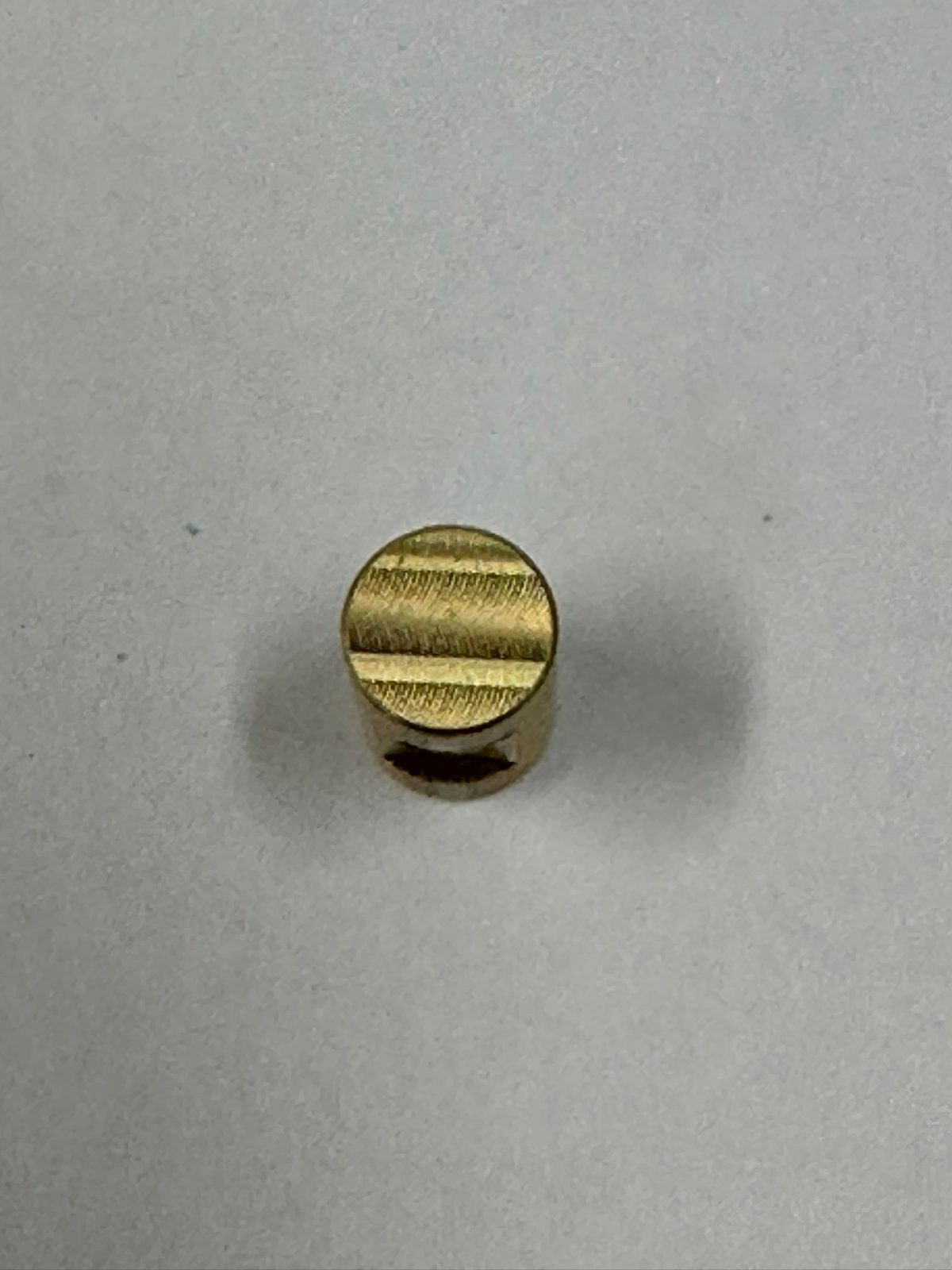
Mirror Mounts
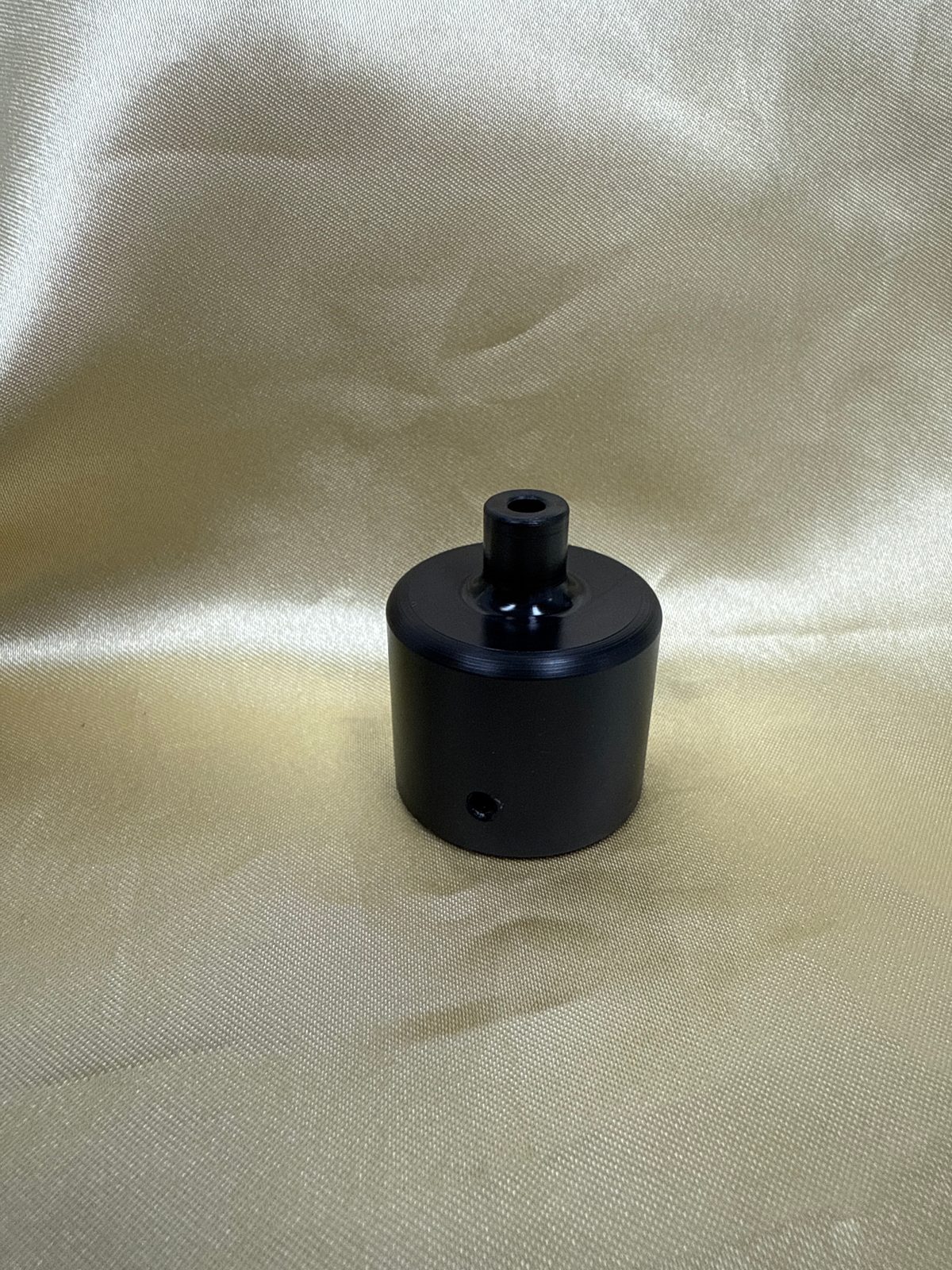
Spectrometer Components
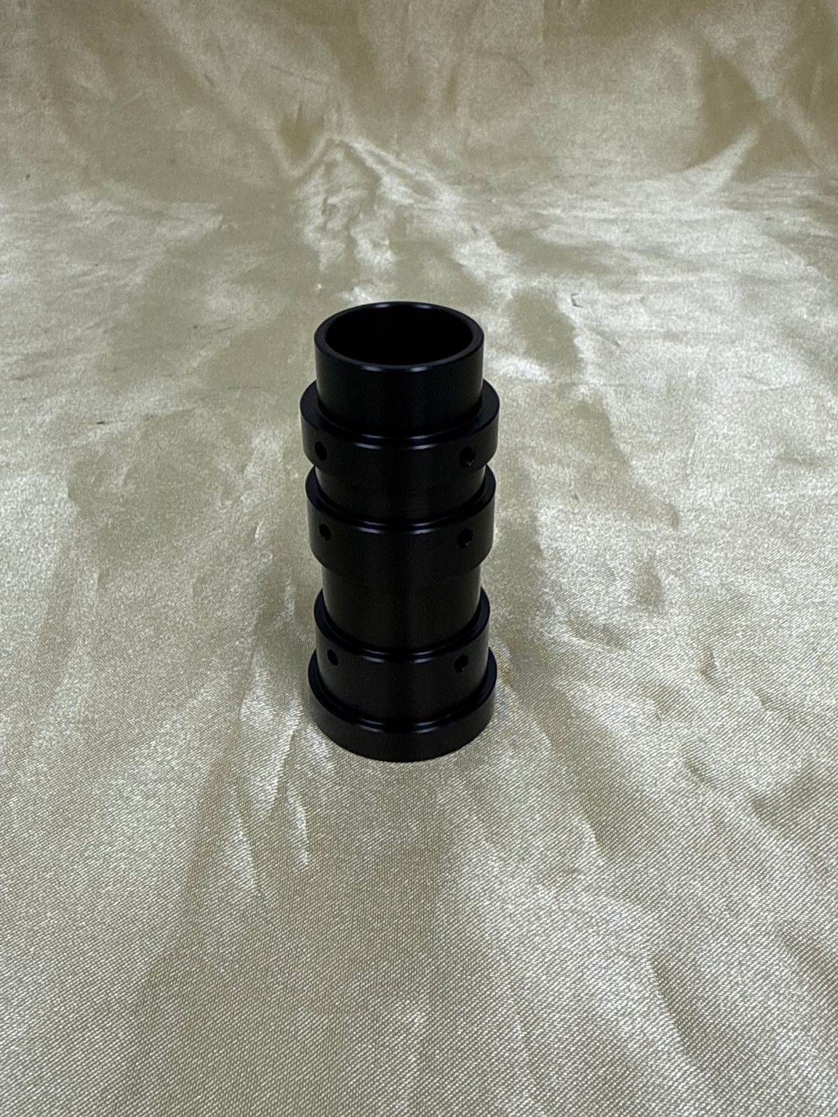
Precision Alignment Stages
Custom Optical Fixtures
Upload a STEP file and an engineer will review and quote it within 24 to 48 hours.
Upload for Review →Problems We Prevent
A general machine shop treats an optical mount like any other bracket. These are the three mistakes that follow most often.
Surface Finish
A bore machined to the wrong finish contaminates the optical assembly.
Photonics bores need Ra 0.4 µm or better, and sometimes an electropolished surface for optical contact. A supplier who misses this can hold the tolerance and still ruin the assembly.
Ra and finish requirements are set during DFM, before manufacture.
Coating Compatibility
The wrong anodize type interferes with optical coatings and cement adhesion.
Type III hard anodize and Type II clear anodize are not interchangeable in optical environments. Most suppliers apply their standard anodize, and the difference shows up in the lab.
Anodize type, thickness and masking are confirmed for every optical part.
Tolerance Stack-Up
Every part passes inspection, and the assembled system is still out of alignment.
Photonics assemblies stack tolerances across several components. Reviewing one part at a time misses errors that only appear at integration.
Engineers check multi-part assemblies for stack-up during DFM.
How a Photonics Order Works
Each order gets an optical review before any cutting starts, and the documents ship with the parts.
- 1Quote in 24 to 48 hoursUpload a STEP File and Drawing
STEP, IGES or a 2D drawing. Include surface finish callouts and any assembly context. An NDA is available on request.
- 2Optical DFM Review
Beyond machinability, your engineer checks bore finish, anodize type, tolerance stack and assembly fit. Issues are raised before cutting starts.
- 3Material and Finish Confirmed
Alloy grade, anodize type and thickness, masking and special handling are confirmed and written into the work order before the order is confirmed.
- 4Manufacture and In-Process QC
5-axis CNC machining with in-process dimensional checks and CMM inspection of critical features. Surface finish is verified at the supplier, before the parts ship.
- 512 days standardDelivery with Documentation
A CMM inspection report, material certificate (EN 10204 3.1), finish confirmation and dimensional report ship with every order, tracked to your door.
Results
"Factorem's engineering team identified a DFM issue that would have caused rework on our first batch. That single review saved us three weeks and significant cost."
- ISO 9001:2015 quality management
- RoHS and REACH compliance available
- EN 10204 3.1 material certs on request
Frequently Asked Questions
If your question is not here, an engineer can answer it directly.
What tolerances can you hold for optical housings and lens mounts?
±0.005 mm as standard for optical housings, kinematic stages and lens mounts. Critical optical interfaces that need sub-micron alignment can be machined to ±0.002 mm on request.
What surface finishes are available for optical assemblies?
Ra 0.4 to 1.6 µm is included as standard. Ra 0.1 µm is achievable with extra processing for reflective or mating optical surfaces. Black hard anodize is available to suppress stray light in optical enclosures.
Which materials do you machine most for photonics?
AL 6061-T6 and AL 7075-T6 for standard housings, Invar 36 for thermally stable mounts where the CTE has to match glass, SS 316L for corrosive or cleanroom environments, and PEEK for electrical isolation. Titanium is available for space-grade parts.
How do you protect sensitive IP during quoting?
Files are encrypted at rest and in transit, and an NDA can be signed before you upload. Only the engineers assigned to your quote see the files, and designs are never shared with third parties without written authorisation.
What are typical lead times for photonics prototypes?
CNC-machined prototypes typically ship in 5 to 10 business days, and SLA or resin 3D-printed parts in 3 to 5 days. Rush lead times can be arranged, so tell us the deadline.
Source Your Next Photonics Component
Upload a STEP file and drawing. An engineer reviews bore finish, anodize type and tolerance stack-up, and the quote arrives in 24 to 48 hours.
