3D Printing for Geometry That Starts Where Machining Stops.
Factorem offers SLA, SLS, FDM, and metal powder bed fusion — with engineer review, process selection guidance, and post-processing to meet your tolerance and finish requirements.
5 processes
FDM · SLA · SLS · MJF · DMLS
±0.1mm
Typical as-printed tolerance
3–10 days
Standard lead time
ISO 9001
Certified
Choose Your Process
Additive Processes
Not sure which process fits your part? Our engineer will recommend — this is a starting guide. Many parts suit more than one option.
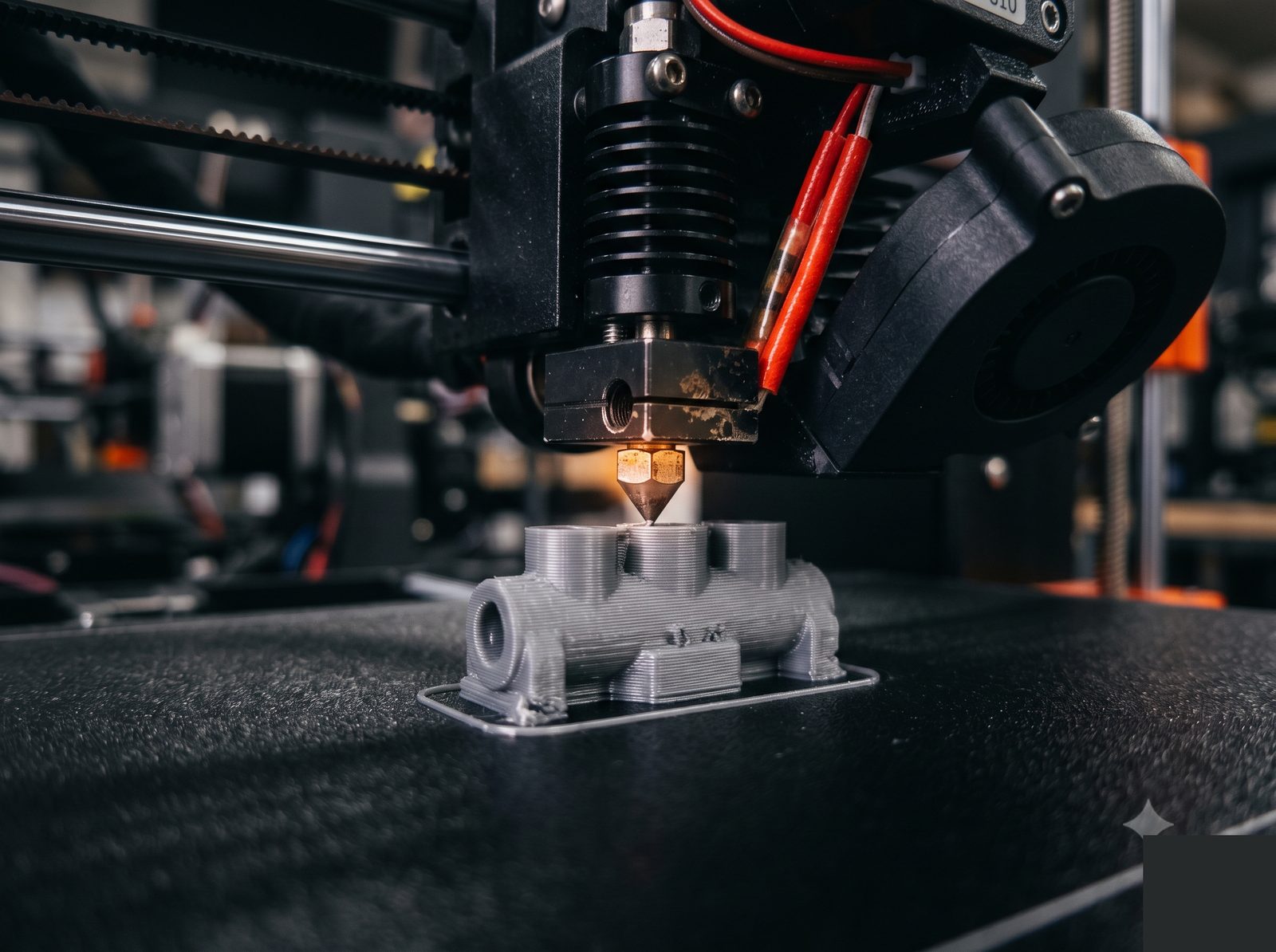
Fused Deposition Modelling
Filament extrusion — fastest and most cost-effective process. Wide material range from standard PLA to engineering-grade PEEK. Best for early-stage prototyping, jigs, and fit-check models.

Stereolithography
UV-cured photopolymer resin. Excellent surface finish and fine feature resolution — the go-to process for visual prototypes, optical covers, and parts where surface quality matters.
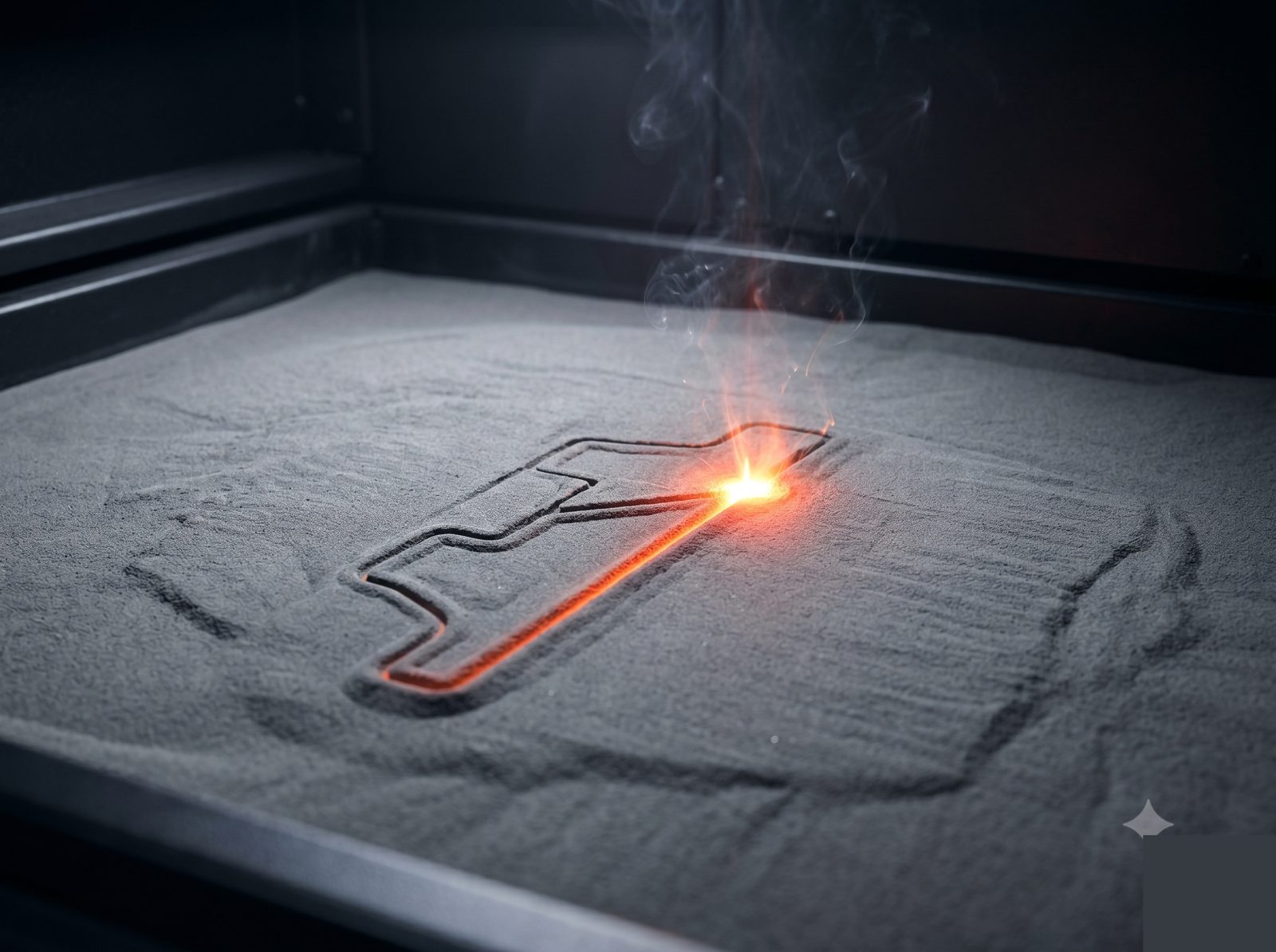
Selective Laser Sintering
Laser-sintered nylon powder — no support structures required. Enables complex internal channels, lattice structures, and snap-fit assemblies that are impossible to mold or machine.
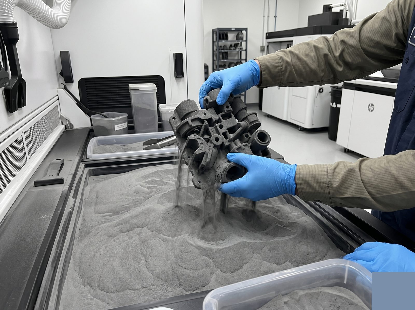
Multi Jet Fusion
HP industrial powder bed process. Produces dense, fine-grained PA12 parts with better surface finish and isotropic mechanical properties than SLS. Well-suited for production-quality functional parts.
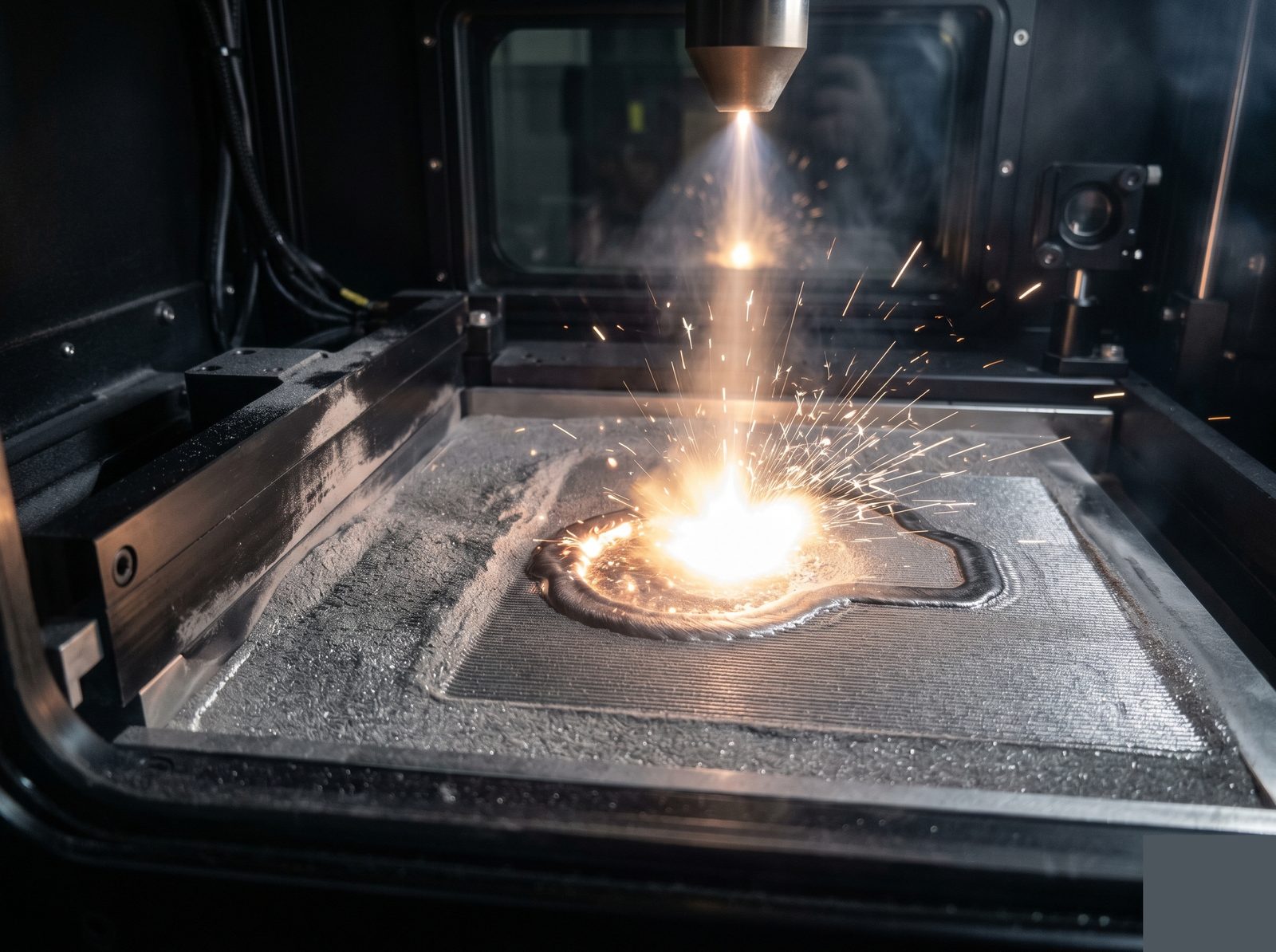
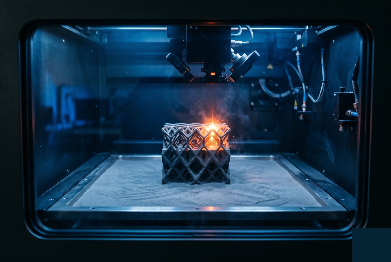
Metal Powder Bed Fusion
Laser-melted metal powder for fully dense metal parts. Ideal for complex internal channels, topology-optimised structures, and geometries that are difficult or impossible to machine.
Not Sure, or Need Something Else?
PolyJet, binder jetting, directed energy deposition — our network covers more than the five processes above. Tell us your application and requirements and our engineer will recommend the right approach.
Common Materials
Materials available across our additive processes. Specific grades and proprietary resins available on request — tell us your application and we'll advise.
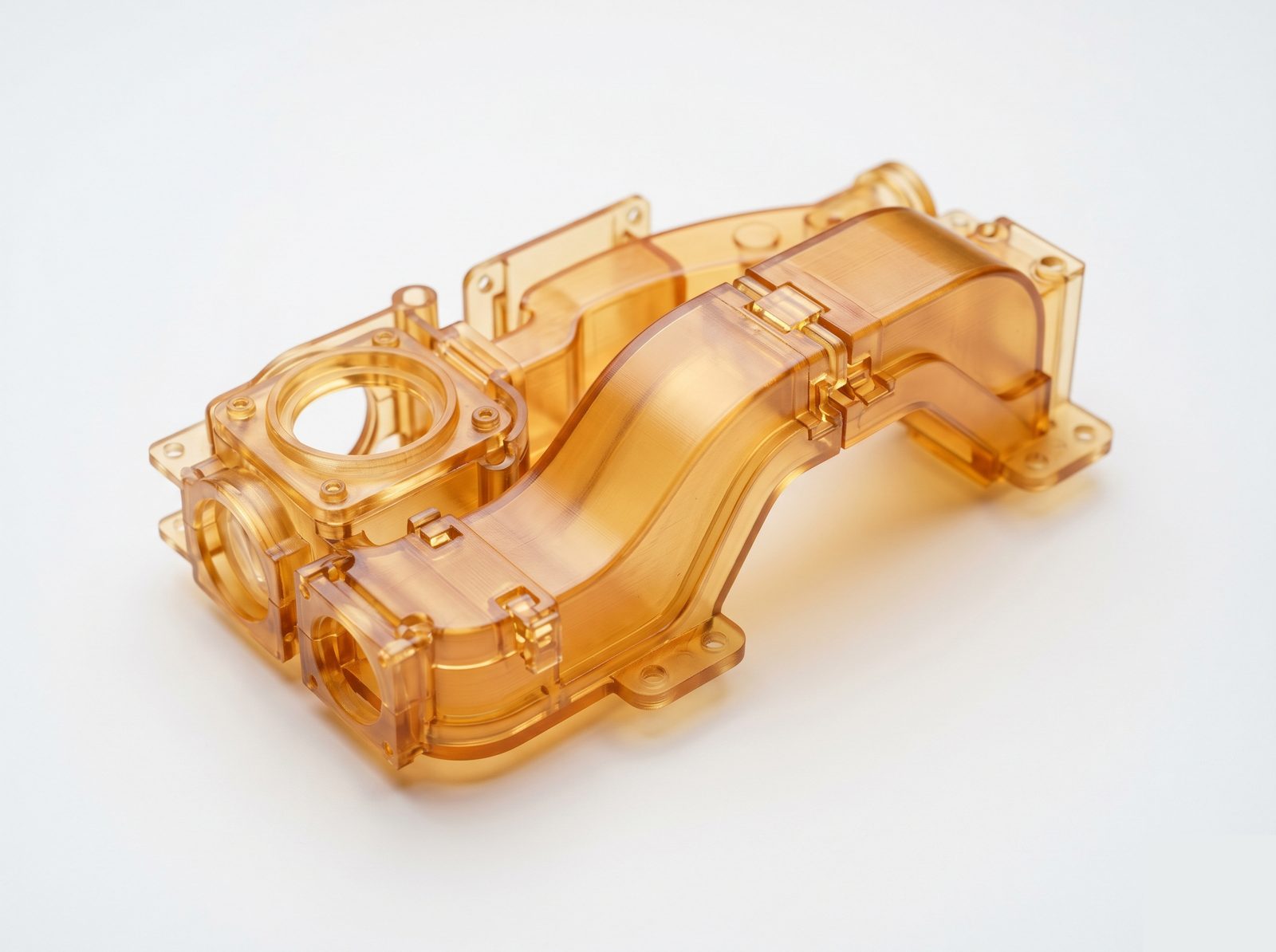
Standard & Engineering Resins
General-purpose, rigid, flexible, and high-temperature resins. Castable wax resins for investment casting patterns also available.
Commonly used for
Visual prototypes, enclosures, optical lens covers, form/fit models
PA12 Nylon / PA11 / TPU
PA12 for functional structural parts; PA11 for higher impact resistance and flexibility. TPU for flexible components requiring deformation under load.
Commonly used for
Air ducts, cable management, snap-fit assemblies, complex brackets
PLA / ABS / PETG / ASA / PEEK
Standard engineering filaments through to high-performance PEEK for chemically resistant or high-temp functional parts. Carbon-fibre filled variants available.
Commonly used for
Early-stage prototypes, jigs and fixtures, thermal break inserts
SS 316L
Austenitic stainless — corrosion resistant, vacuum-compatible, biocompatible. Density >99% after printing. Post-print CNC for critical features.
Commonly used for
Complex fluid manifolds, vacuum components, medical hardware
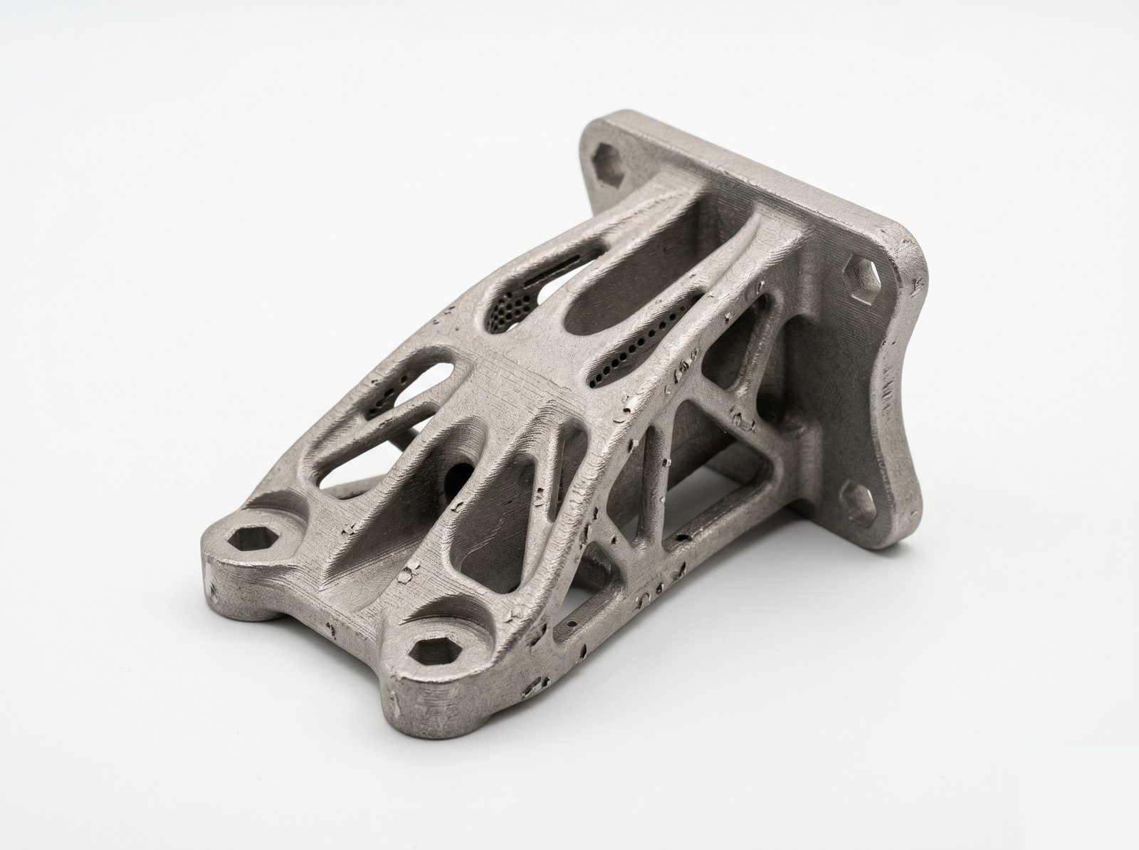
Ti-6Al-4V
Titanium alloy powder — excellent strength-to-weight, biocompatible, low CTE. Best for topology-optimised aerospace structures that are impractical to machine.
Commonly used for
Lightweight structural members, lattice-infill brackets, biomedical implants
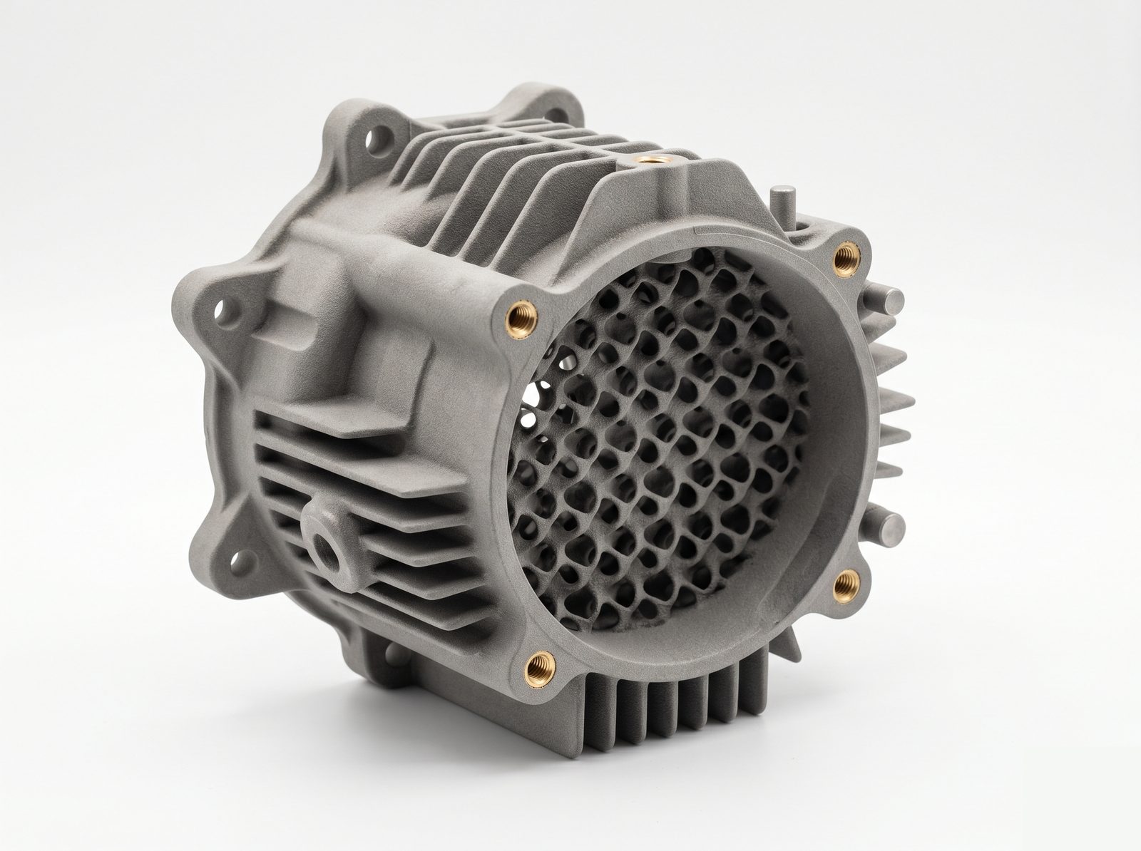
AlSi10Mg
Aluminium-silicon-magnesium alloy. Lightweight, good thermal conductivity, suitable for heat sinks and structurally optimised enclosures with internal channels.
Commonly used for
Complex heat exchangers, conformal cooling channels, weight-optimised housings
Need a different metal alloy — Inconel, copper, tool steel, cobalt chrome — or a specialist polymer? Contact us. Our network covers a broader material range than shown here. Talk to an engineer →
Don't see what you need?
Exotic material, unusual geometry, or a process you've heard about but aren't sure we do? Our engineers are happy to advise. Most reasonable requests can be accommodated.
Industries & Applications
Additive manufacturing is used across Factorem's verticals — commonly for prototyping alongside CNC-machined production parts, and for geometries that simply can't be machined. Not limited to these examples.
Photonics & Optics
Prototype lens mount housings, custom cable management for optical setups, non-structural covers and enclosures for bench instruments
See Photonics page →
Quantum
Rapid prototyping of vacuum system components before committing to machined versions; complex support structures for cryogenic setups
See Quantum page →
Robotics
Gripper jaws, cable routing brackets, custom sensor mounts, rapid end-effector iterations before machining production versions
See Robotics page →
Defense & Aerospace
Topology-optimised metal brackets, conformal cooling channels in housings, non-structural thermal shields — EAR99 commercial programs
See Defense page →
Space Tech
Lightweight lattice-infill structural members for small satellites, complex titanium deployment mechanism brackets, rapid prototyping of separation hardware
See Space Tech page →
Other Industries
Medical devices, semiconductor equipment, industrial automation — additive manufacturing applies wherever geometry complexity or low volume makes machining impractical.
From Our Build Plate
Design Considerations
Before You Send Your File
Common design factors for 3D printed parts. Guidance, not rigid rules — send your design and our engineer will advise on the best approach regardless.
Minimum Wall Thickness by Process
SLA: 0.5mm minimum; SLS/MJF: 0.7mm; FDM: 1.2mm (2 perimeters); DMLS metal: 0.4mm. Thinner walls are sometimes achievable but risk failure or warping — flag them in your brief.
Build Orientation Affects Strength & Finish
All additive processes are anisotropic — parts are stronger in X/Y than in the Z (layer) direction. Tell us the primary load direction and which faces are cosmetic; we'll orient accordingly.
Tight Tolerances: Allow for Post-Machining
Interface bores, sealing faces, or threads tighter than ±0.1mm should include +0.3–0.5mm stock allowance on critical surfaces for CNC post-machining. Print the geometry, machine the interfaces.
Metal Prints: Design for Support Removal
DMLS/SLM requires supports on overhangs >45° from vertical — these must be removable after printing. Design access ports and expect rougher finish where supports attach on interior surfaces.
Complex geometry — internal lattices, overhangs, or features you're not sure are printable?
Talk to our engineersHow an Additive Order Works
Upload Your File
Send STEP, IGES, or STL. Include your requirements: process preference (if any), material, finish, tolerance callouts, and quantity. Not sure on process? Just send the file and describe the application — we'll recommend.
Process Selection & DFM Review — Within 24 Hours
A Factorem engineer reviews your geometry, selects the optimal process (or confirms yours), identifies any printability concerns, and advises on build orientation and post-processing strategy.
Confirm Quote, Process, & Post-Processing
Fixed-price quote including post-processing steps. Confirm material, finish spec, and any post-machining requirements for critical features.
Print, Post-Process, & Inspect
Parts printed, support-removed, and post-processed to spec. Critical dimensions inspected. Metal prints also go through stress relief and, where specified, HIP treatment.
Documentation & Delivery
Certificate of Conformance on every order. Dimensional inspection report for critical features. Material data sheet and, for metal prints, density certification on request.
3D Printing FAQ
We offer SLA (stereolithography), SLS (selective laser sintering), FDM (fused deposition modelling), and DMLS/SLM (metal powder bed fusion). The right process depends on your material requirements, tolerance needs, part size, and whether the application is prototype or production. Our DFM review will recommend the most appropriate process for your part.
Tolerances vary by process. SLA typically holds ±0.1mm. SLS and DMLS hold ±0.1–0.2mm as-printed; critical features are often post-machined to ±0.01–0.05mm. FDM is ±0.2–0.5mm and best suited for non-critical features. If your part has tight tolerance requirements, tell us during the brief and we'll specify the right process or hybrid approach.
Yes. We offer DMLS / SLM for metal parts in SS 316L, Ti-6Al-4V, AlSi10Mg, and other alloys on request. Metal 3D printing is well-suited for complex internal channels, topology-optimised structures, and geometry that's difficult or impossible to machine. Post-print CNC machining of critical features is often combined with metal printing.
3D printing is the right choice for: complex internal channels or lattice structures impossible to machine, rapid prototype iteration, low volume where tooling cost would be prohibitive, and topology-optimised lightweight structures. CNC machining is better for: tight tolerances (±0.01mm or better), high-volume production, demanding surface finishes, and materials not available in additive form. For many programs, the answer is a hybrid — print for geometry, machine for interfaces.
Yes. Post-processing includes support removal, surface finishing (sanding, polishing, media blast), painting, CNC post-machining of critical features, and plating or anodizing where the substrate is compatible. For metal prints, stress relief heat treatment and HIP (Hot Isostatic Pressing) are available on request through our supplier network.
We accept STEP, IGES, and STL. For metal printing, STEP is strongly preferred as it preserves accurate geometry for post-machining reference. STL tessellation errors can cause print artifacts — if you only have STL, we'll inspect it during DFM review and advise. If you don't have a CAD file, describe your part and we can discuss reverse engineering or design support.
Ready to Print Your Next Part?
Upload your file for process selection and a DFM review. Or talk to an engineer about whether 3D printing, machining, or a hybrid is the right approach.
Process recommendation within 24 hours · Fixed-price quote · Certificate of Conformance on every order