
5-Axis Machining
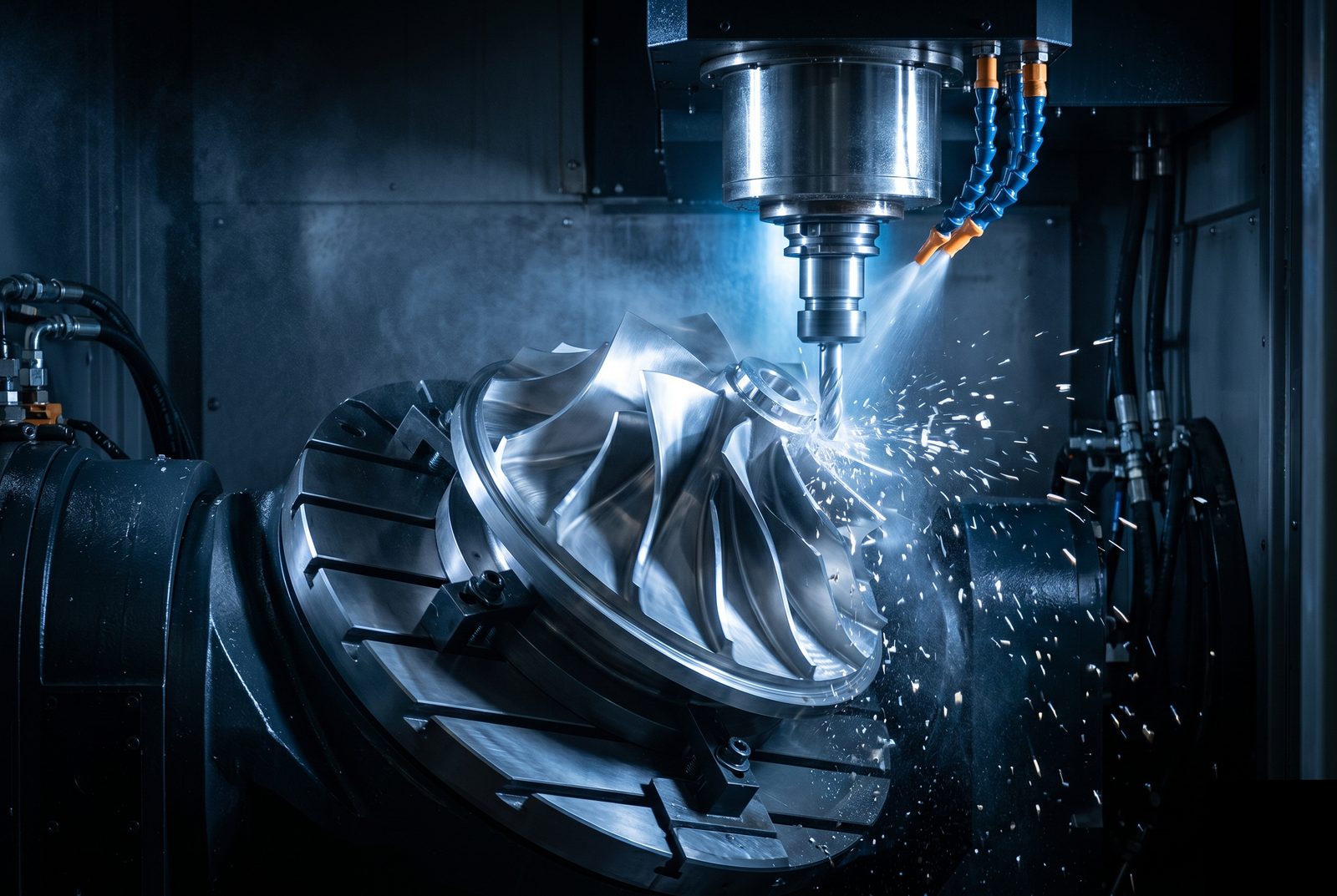
Parts with undercuts, compound angles and multi-face features, machined in one setup from aluminium, titanium, stainless steel, Invar 36 or PEEK. With no datum shift between setups, true position across faces holds to ±0.01 mm or better.
Specifications
Typical limits for 5-axis work. Many jobs go past these numbers, so send the file and an engineer will tell you what is achievable.
Axis Strategy
Choose 5-axis for undercuts, compound angles, features on several faces or freeform surfaces. If you are not sure, send the file and the DFM review will specify the approach.
| Part requirement | 3-axis | 5-axis |
|---|---|---|
| Multi-face features | Multiple setups | Single setup |
| Positions across faces | Setup error accumulates between setups | No datum shift. True position ±0.01 mm or better |
| Curved and freeform surfaces | Ball-end milling leaves a scallop pattern | Tool held at the optimal angle through the cut, Ra 0.4 to 1.6 µm |
| Titanium and hardened steels | More tool wear and lower surface quality on curved features | Constant tool engagement angle keeps chip load steady and extends tool life |
Materials
5-axis uses the same materials as 3-axis CNC. Titanium and other high-strength alloys gain the most, because a constant tool engagement angle reduces tool wear.
Aluminium 6061-T6 and 7075-T6
Most 5-axis aluminium work. 7075 for high-strength flight hardware, 6061 for enclosures, mounts and optical hardware.
Titanium Ti-6Al-4V
A constant tool angle holds chip load, extends tool life and gives a better surface on curved features than 3-axis.
Stainless Steel 316L and 17-4 PH
Vacuum-compatible and high-strength grades. Complex cavities and undercuts for vacuum parts are cut in one setup.
Invar 36
Near-zero CTE for thermally stable optical and quantum lab hardware. Hard to machine. 5-axis reduces total cutting time and fixturing work.
PEEK and Ultem
Engineering polymers for electrical isolation and thermal management. Contoured profiles are cut in one setup.
Copper, Kovar and Hardened Tool Steels
Reviewed case by case with other alloys. Send the material and geometry, and an engineer will advise on machinability, tool strategy and lead time.
Finishes
Every CNC finish is available on 5-axis parts. Send your spec sheet and an engineer will confirm it.
| Finish | Standard | Notes |
|---|---|---|
| As Machined | None | Ra 0.4 to 1.6 µm on curved surfaces at the optimal tool angle, better than 3-axis on freeform |
| Anodize, Type II and III | MIL-A-8625 | All aluminium parts. Hard anodize for wear-critical surfaces on complex geometry |
| Chromate Conversion | MIL-DTL-5541 | Conductive, corrosion-resistant coating for aluminium parts that need EMI grounding |
| Passivation | ASTM A967 | Stainless steel. Removes free iron contamination, which matters for parts used in vacuum |
| Electroless Nickel | None | Even coating over complex curved geometry, an advantage over electrolytic plating |
| Bead Blast | None | Even matte finish on all faces, compound curves included. Often specified before anodizing for a consistent appearance |
| Precision Grinding | None | Ra 0.1 to 0.2 µm on flat datum faces after 5-axis machining. For sealing surfaces and optical-grade references |
| On Request | Your spec | Black oxide, gold plating, PVD coatings, specialty aerospace coatings |
Design Rules
Treat these as guidance. If your geometry does not fit them, send it anyway and an engineer will advise.
Undercuts and Angled Features
Annotate undercut depths, angled bore directions and compound angles on the drawing, so the toolpath is planned before the quote.
Leaving them unmarked, so geometry constraints turn up mid-job instead of at quoting.
Tolerances Across Faces
State tight positional relationships between faces explicitly on the drawing. Callouts of ±0.02 mm or tighter across faces rely on the single setup.
Leaving cross-face relationships off the drawing, with each face dimensioned on its own.
Freeform Surfaces
Send the STEP model, because for compound-curved and freeform geometry it is the drawing. Add Ra callouts and any curvature tolerances for those faces.
Relying on 2D section views. They do not capture enough of the surface.
Fixturing Access
Give the part a secure clamping face that leaves every machined surface reachable on the rotary table.
Very large flat parts, or parts with no good clamping face, sent without a flag. They may need a custom fixture.
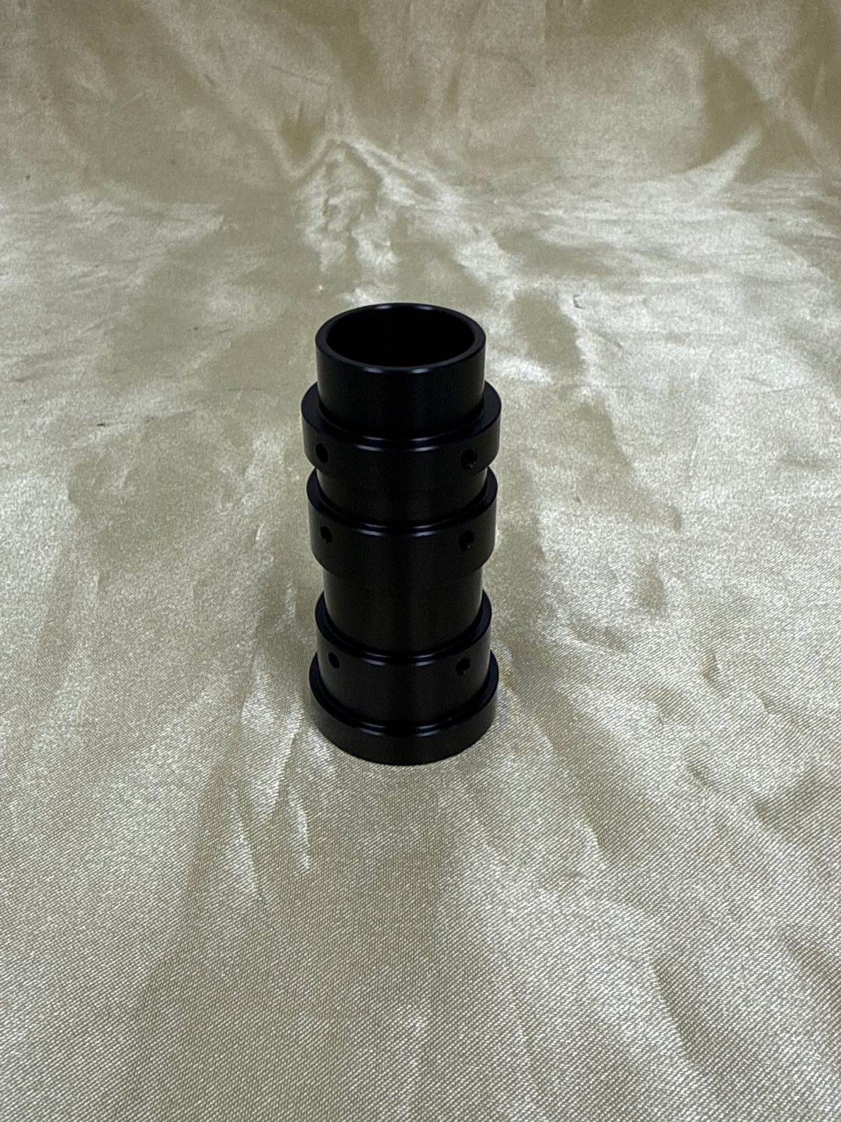
Machined Parts
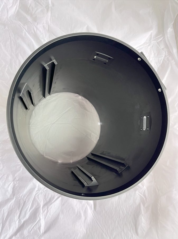
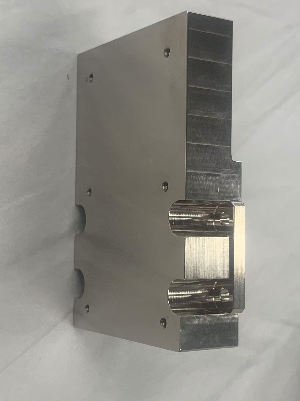
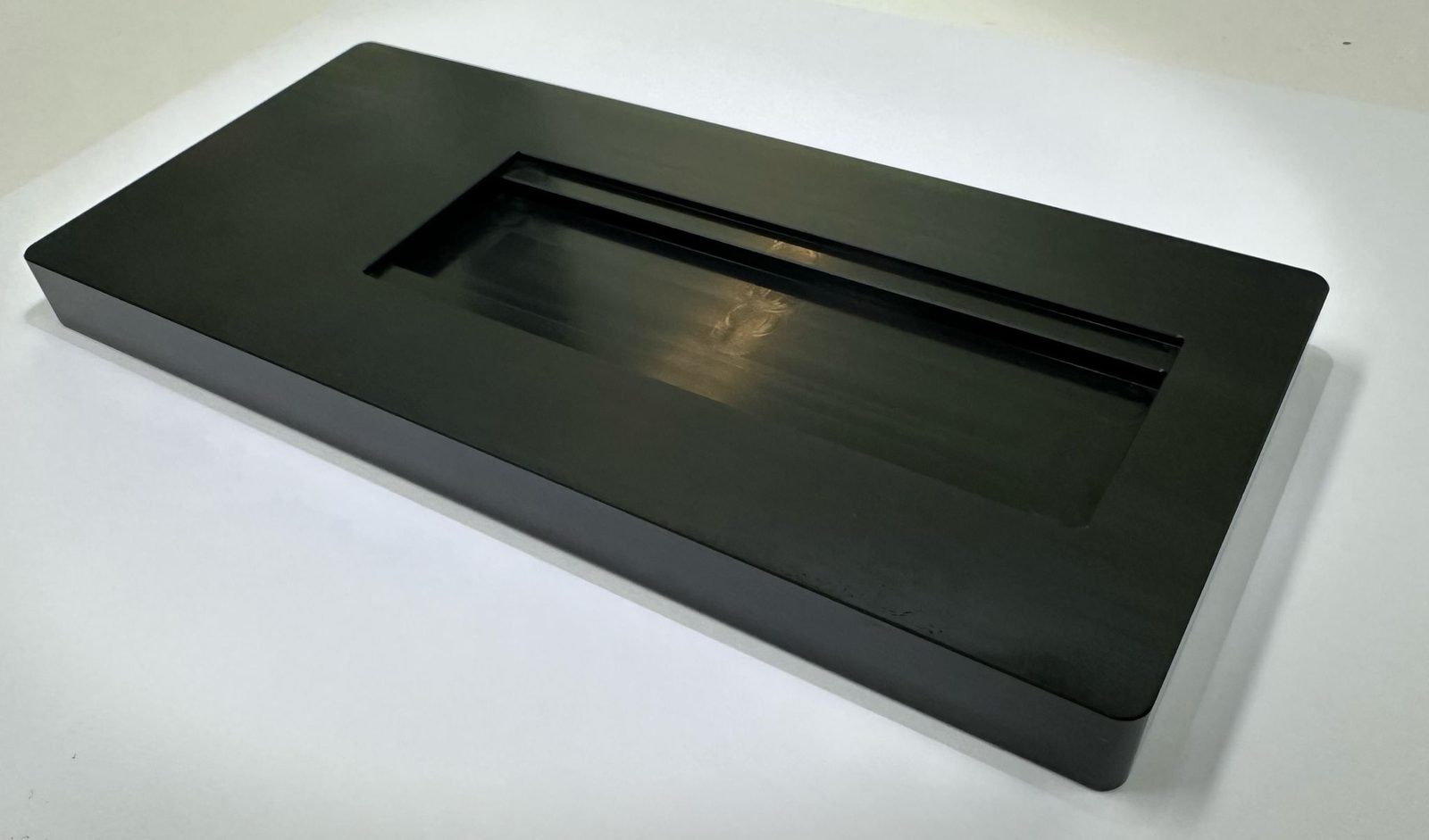
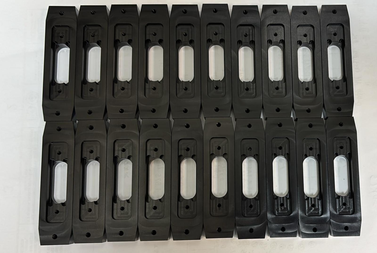
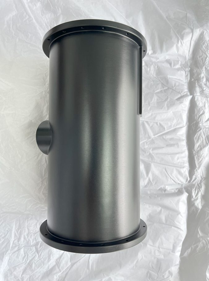
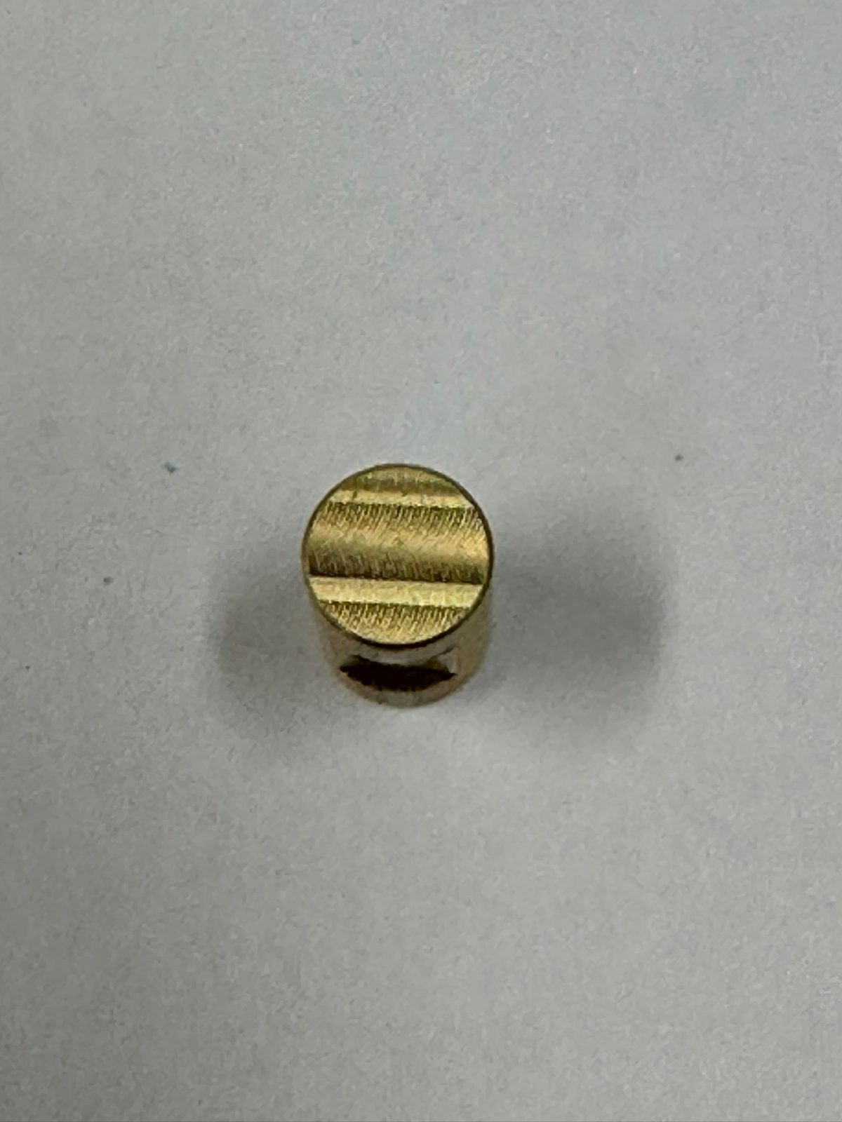
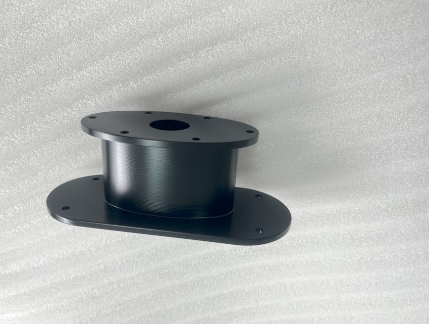
Parts from Factorem's CNC work. Each caption gives the material, finish and industry.
From Upload to Delivery
Every 5-axis part gets an engineer review before the price is fixed. Complex geometry can take the full 48 hours.

Upload Your CAD File
Send STEP or IGES with your drawing. Mark critical tolerances, angularity callouts and undercut depths so the engineer has full context.

DFM Review and Quote
An engineer reviews the design, chooses indexed or simultaneous 5-axis, works out the fixturing and confirms every feature can be reached. You get a fixed price, with lead time and documentation requirements confirmed.
Machining with In-Process Probing
CAM programming starts as soon as you confirm the order. On-machine probing checks critical features at each rotary index position.

CMM Inspection
First articles are CMM inspected against your drawing, including every angular and true-position callout.

Documentation and Delivery
Tracked shipment with a full dimensional inspection report, certificate of conformance, and MTR where it applies.
What Ships with the Parts
- Dimensional inspection reportEvery order
- Certificate of conformanceEvery order
- MTRWhere it applies
Start with Your CAD File
Send a drawing too, with critical tolerances, angularity callouts and undercut depths marked.
Upload CAD for a QuoteIndustries
5-axis parts also go into medical implants, turbomachinery, semiconductor equipment and custom instrumentation.
Frequently Asked Questions
If your question is not here, an engineer can answer it directly.
When do I need 5-axis instead of 3-axis machining?
When the part has undercuts, compound angles, multi-face features that would need several 3-axis setups, or freeform surfaces such as turbine blades and compound-curved housings. It is also the choice when tight angularity or positional tolerances link features on different faces, because a single setup does not accumulate setup error. If you are not sure, send the file and the DFM review will specify the approach.
What is simultaneous 5-axis and when is it needed?
All five axes move at once, so the cutter can follow freeform surfaces with constant tool engagement. It is needed for turbine blades, impellers, compound-curved optical housings and similar geometry. Most undercut and multi-face parts can use indexed 5-axis (3+2) instead, at lower cost. The DFM review decides which your part needs.
What tolerances can you hold on 5-axis machined parts?
±0.005 mm on critical features. A single setup removes datum shift between setups, so features on different faces keep their positional relationship better than on multi-setup 3-axis parts. True position across faces is typically ±0.01 mm or better, and rotary axis angular repeatability is ±0.01°.
What part geometries are best suited to 5-axis?
Undercuts, angled holes and pockets, compound-curved surfaces, parts machined on 4 or more faces, and tight true-position tolerances across faces. Curved surfaces also finish better: the tool holds its optimal angle through the cut, which lowers scallop height and improves Ra compared with 3-axis ball-end milling.
What materials can you 5-axis machine?
The same range as 3-axis CNC: aluminium 6061 and 7075, Ti-6Al-4V, stainless steel 316L and 17-4 PH, Invar 36, PEEK, and others on request. Titanium and hardened steels gain the most, because a constant tool engagement angle reduces tool wear and improves surface quality.
Do you offer indexed (3+2) as well as simultaneous 5-axis?
Yes. Indexed 5-axis positions the part at a fixed angle, then cuts with 3-axis motion. It handles most undercut and multi-face work with less programming time and cost. Simultaneous 5-axis is for freeform surfaces and geometry where the tool angle must keep changing relative to the surface. The DFM review picks the approach for your part and budget.
Price a 5-Axis Part
Factorem has made parts for 300+ engineering teams, with 98% of orders delivered on time and 99% of parts accepted.
