
Injection Molding
Enclosures, housings and structural plastic parts molded in ABS, PC, nylon, PP and PEEK. An engineer reviews your design within 24 hours, and you approve the first shots before the production run.
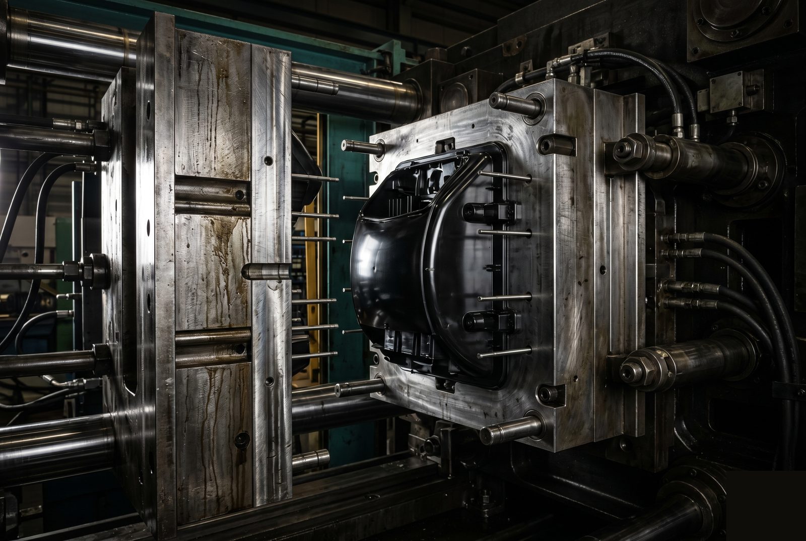
Specifications
Typical limits. Final specs depend on material, geometry and tooling, and an engineer confirms them during the DFM review.
Molding Processes
Standard injection molding covers most enclosures, housings and structural parts. The other three suit silicone, two-material and hollow parts.
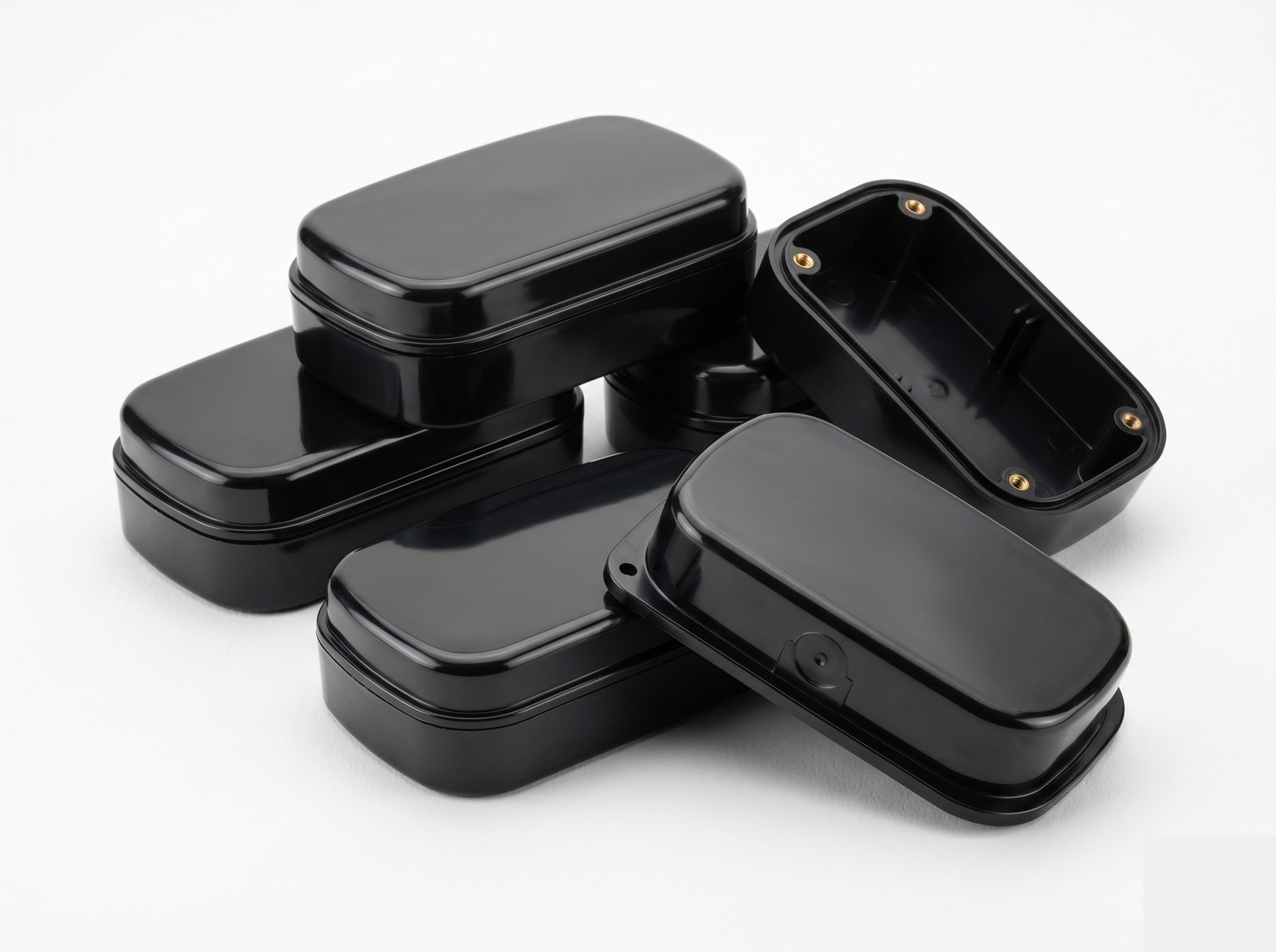
Custom Plastic Injection Molding
Thermoplastic resin injected into a custom steel or aluminium tool to make consistent parts at volume. Used for most plastic enclosures, housings and structural parts.
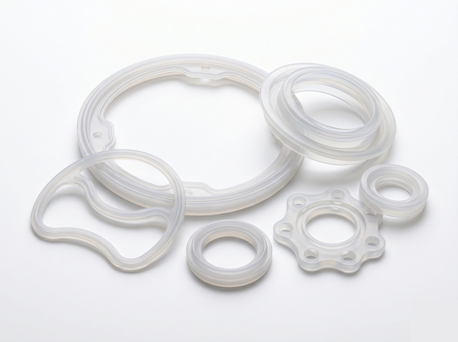
Liquid Silicone Rubber (LSR) Molding
Two-part platinum-cured silicone injected into a temperature-controlled mold. Makes flexible, biocompatible parts with very good chemical and temperature resistance.
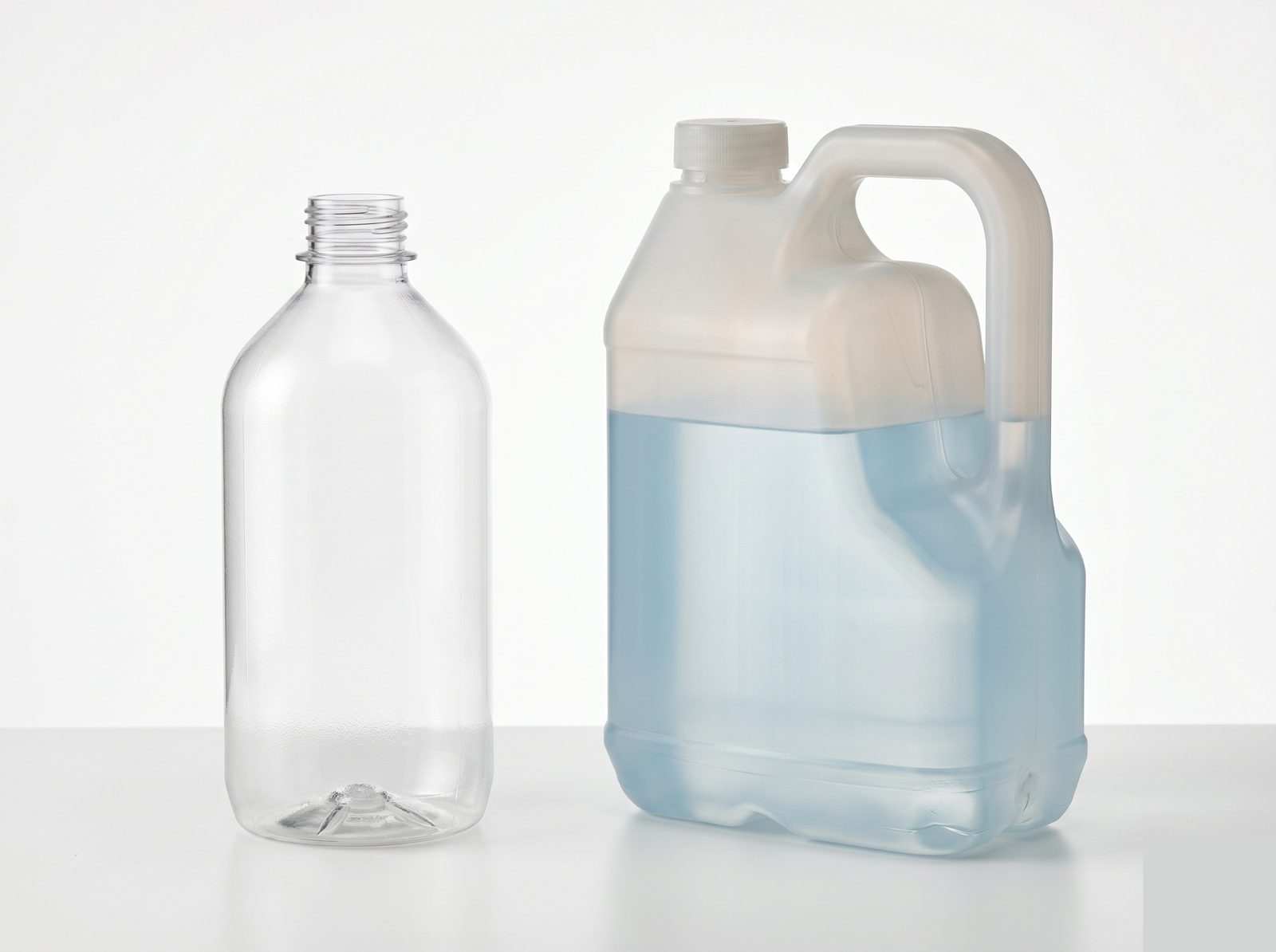
Blow Molding
A heated plastic parison is inflated inside a mold to make hollow parts. Suits bottles, tanks and enclosed duct shapes that conventional injection tooling cannot produce.
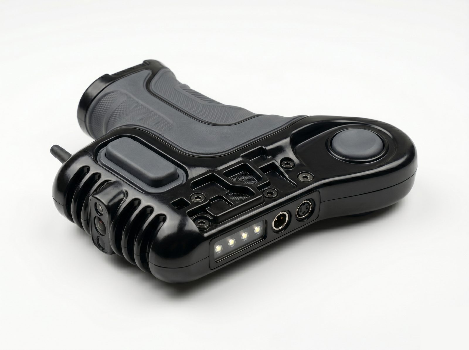
2-Shot / Overmolding
Two materials, typically a rigid substrate and a soft overmold, are molded in sequence in one tool (2-shot) or two (overmolding). The result is one two-material part with no adhesive or assembly.
Materials
Commonly used engineering plastics. Other grades, colours and filled variants are available on request.
ABS
Good impact strength, easy to mold, and takes a wide range of surface finishes and paints. The standard choice for consumer electronics housings, equipment enclosures and prototype parts.
Polycarbonate (PC)
High impact strength, dimensionally stable, and optically clear in natural grade. UV-resistant grades are available. PC/ABS blends improve impact strength and process more easily than unfilled PC.
Nylon PA66 and PA6
High strength to weight, with good chemical and fatigue resistance. Glass-filled grades such as PA66-GF30 are stiffer and creep less. Nylon absorbs moisture, which affects dimensions and processing.
PEEK
Thermal stability for continuous use to 250 °C, plus chemical resistance and mechanical strength. Its processing temperature needs suitable tooling and equipment, and it is costly, so it is best kept for parts cheaper plastics cannot handle.
Polypropylene (PP)
Light, chemically resistant and fatigue resistant, which makes it a good fit for living hinges and snap fits. Less stiff than ABS but cost-effective at high volume.
Other Materials and Overmolding
PPS, LCP, acetal (POM), TPU and TPE for overmolding, and glass- and carbon-filled variants. Share the material requirement and application, and an engineer will advise on suitability and processing.
Tooling
Each quote is a fixed price for the tool and the production run. Tooling cost is amortised across the run, so unit cost falls at volume.
Aluminium Tooling
Shorter lead time. For parts that can tolerate slightly looser tolerances, it is often the right choice for early production quantities too.
Steel Tooling
Lead time depends on part complexity. PEEK, PPS, LCP and other high-performance plastics need appropriate tooling steel and process controls.
First shots are measured against your drawing and reviewed with you before production begins.
Design Rules
Guidance rather than fixed rules. Send the design either way: the DFM review checks every part, including multiple undercuts, tight tolerances and unusual materials.
Draft Angles
Add 1 to 3° of draft to faces parallel to the pull direction so the part releases cleanly. Textured surfaces typically need 3 to 5°.
Zero-draft faces. They are possible with side-pulls, but add tooling cost.
Uniform Wall Thickness
Keep walls uniform, between 1.0 and 4.0 mm. Where a thick section is unavoidable, core it out to cut mass without losing stiffness.
Thick sections. They cool unevenly and cause sink marks or warpage.
Gates and Parting Line
Place gates on non-cosmetic surfaces where possible, and confirm the parting line location early.
Gates on cosmetic faces, or a parting line left until late. Gate marks are visible, and the parting line sets where the seam sits and where flash can form.
Undercuts and Side Features
Where possible, redesign undercuts to form through or to be reachable from the parting line.
Undercuts that block straight ejection. They need side-pulls, lifters or collapsible cores, which add tooling cost.
From Upload to Delivery
Issues are flagged with suggested fixes before any tooling cost is committed, and production starts only after you approve the first shots.

Upload Your Part File
Send STEP with your drawing, plus the material, colour, surface finish and any insert or overmolding specs. For assemblies, include the mating context.

DFM Review and Quote
An engineer reviews draft angles, wall thickness, gate placement, parting line, undercuts and material suitability, and flags any issues with suggested fixes. A fixed price covers tooling and the production run. Confirm aluminium or steel tooling, resin grade, colour and first article requirements.
Tool and First Shots
The tool is machined and first shots are produced. Once you approve them, process parameters are locked for consistent parts and the run begins.

First Shot Inspection
First shots are measured against your drawing, and you approve them before the run begins. An FAI report is available.
Documentation and Delivery
Certificate of conformance and dimensional inspection report on every order, plus material certification from the resin supplier. Parts ship tracked with a full handover pack.
What Ships with the Parts
- Certificate of conformanceEvery order
- Dimensional inspection reportEvery order
- Material certificationFrom the resin supplier
- FAI reportAvailable
Start with Your CAD File
Add the material, colour, surface finish and any insert or overmolding specs.
Upload CAD for a QuoteIndustries
Used wherever consistent plastic parts are needed at volume, including medical device enclosures, semiconductor tooling inserts and industrial automation components.
Frequently Asked Questions
If your question is not here, an engineer can answer it directly.
What tolerances can you achieve with injection molding?
±0.1 to 0.2 mm for standard features, depending on material, wall thickness and part geometry. Critical features can be held to ±0.05 mm with appropriate tooling and process control. The DFM review identifies which features need special attention before the tool is cut.
What is your minimum order quantity for injection molded parts?
There is no hard minimum. Orders run from prototype quantities of 50 to 500 pieces to production runs of 10,000+ pieces. Tooling is amortised across the run, so unit cost falls significantly at higher volumes. An engineer can help you decide whether injection molding or 3D printing is more economical for your quantity and timeline.
How long does tooling take?
Aluminium prototype tooling typically takes 2 to 4 weeks, and production steel tooling 4 to 6 weeks depending on part complexity. First shots are reviewed with you before production begins. For parts that can tolerate slightly looser tolerances, aluminium tooling is often the right choice for early production quantities because of its shorter lead time.
Can you mold PEEK and other high-performance engineering plastics?
Yes. PEEK, PPS, LCP and other high-performance materials need higher melt temperatures, controlled tool temperatures, appropriate tooling steel and process controls. Send your material and application, and an engineer will confirm suitability and advise on design requirements.
Can you do overmolding and insert molding?
Yes. Insert molding (metal inserts, threaded brass inserts, pins) and overmolding (soft-touch grip materials, two-material parts) are both available. Insert location and orientation affect tooling design, so specify them early in the DFM process.
What documentation comes with molded parts?
A certificate of conformance, a dimensional inspection report for critical features, and material certification from the resin supplier. An FAI report is available, and a full quality documentation pack can be provided for programs with specific documentation requirements.
Price a Molded Part
Factorem has made parts for 300+ engineering teams, with 98% of orders delivered on time and 99% of parts accepted.
